
A drawing for a CNC turned part comes in with ±0.01 mm on the outer diameter and Ra 0.8 on the sealing face. The buyer’s first question is usually about price; the second — the one that actually decides the price — is how much grinding allowance to leave after turning, and how many grinding passes the tolerance really needs. The answer is not one number. It depends on what the lathe can hold on its own, and this article gives the actual figures we use on the shop floor: why a grinding pass beats a high-precision turning pass on both cost and stability, how much allowance to leave, and why rough grinding and finish grinding are two separate passes.
Why turning alone stops at ±0.02 mm
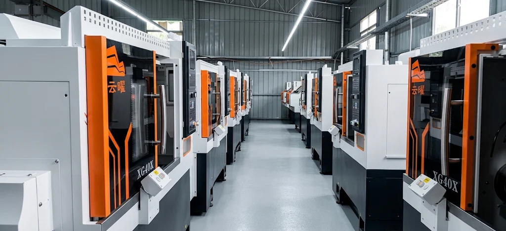
On our own CNC lathes — more than 60 automatic machines on gantry-robot loading lines — a regular turned diameter holds ±0.02 mm without any special measures. That is the economic accuracy of turning, and it is not a machine limitation we could buy our way out of. Three things push the size while the part is being cut:
Heat. A steel part grows about 11.5 µm per metre per degree Celsius. Turn continuously for twenty minutes and the workpiece is several degrees warmer than when it started; on a 100 mm body, a 10 °C rise is roughly 12 µm of diameter — more than the whole ±0.01 mm band. The part measures right at the machine and ships undersize after it cools.
Tool wear. The insert edge wears back continuously, so the diameter drifts outward through a batch — typically 5–15 µm between the first piece and the last one before a tool change. In-process gauging catches the drift, but it does not remove it.
Deflection. On slender parts the cutting force pushes the workpiece away from the tool, and the finished diameter follows the deflection, not the programme. Slower, lighter cuts reduce it — at a cost in cycle time that gets worse the tighter the tolerance gets.
Add the three up and asking a lathe to hold ±0.01 mm across a production batch is asking it to fight physics for every piece. The usual next question is why not simply buy a lathe accurate enough — and the answer is that even then, the grinding route still wins. That comparison is the next section.
Why not just turn it to ±0.01 mm?
First, the machine barrier. Holding ±0.01 mm by turning alone demands a new or high-precision machine tool, and that is a capital barrier most shops do not clear. A large share of the lathes running today in ordinary machining shops are older or budget machines whose geometric accuracy and thermal behaviour were never specified for micron-class work. So the route exists on paper and fails in production — the shop quotes it, then discovers mid-batch that the machine drifts.
Second, even with the right machine, the inspection bill makes it uneconomic. A turning process with no grinding backup cannot trust the machine to stay in band for the whole batch, so every piece — or very nearly every piece — has to be measured individually. That means slow production and a heavy gauge-and-record workload on an operation that was supposed to be the fast one. And stability is worse, not better: the size drifts with heat and tool wear, so rejects appear in every few hundred pieces, and a scrap part that measures just 0.01 mm over can slip into an accepted lot if the inspection is sampling rather than 100%. A single escaped defect costs the buyer far more than any saving on cycle time.
Third, grinding cuts the cost instead of adding to it. A grinder removes the last few microns cold, with a geometry-true wheel, and the size it leaves is the size the part keeps. No thermal accounting, no drift compensation, no per-piece micrometer ritual: one pass through the machine holds the band, and the inspection that remains is a sane sampling plan instead of a 100% filter. On a CNC turned part, the grinding allowance — that thin layer of stock left after turning — is what buys all of this.
A real job that settled the argument. A Ø12 mm diameter with a +0.02/0 mm tolerance band. Quoted as a turning-only job, the shop priced the tighter control at an extra ¥0.30 per piece — with no additional process added; that premium was purely for slowing down, measuring harder, and absorbing the rejects the process was known to produce. Oversize parts running about 0.01 mm out were a routine occurrence on that route.
We took the same part to the grinder instead. The size came out stable batch after batch, and the added cost was ¥0.15 per piece — half the premium of the route that delivered more rejects, which made grinding the cheaper route outright. That single comparison is why, on our floor, ±0.01 mm is a grinding specification, not a turning one — and why the grinding allowance is a line item on the process sheet rather than an afterthought.
| ±0.01 mm reached by | Turning only | Turn, then grind |
|---|---|---|
| Machine needed | New or high-precision lathe | Standard lathe plus a grinder |
| Inspection load | Close to 100%, every piece | Sampling plan |
| Batch stability | Drifts with heat and tool wear | Holds — the pass is cold |
| Escapes | Oversize parts slip into accepted lots | Rare — one pass sets the size |
| Cost, Ø12 case above | +¥0.30 per piece | +¥0.15 per piece |
How much grinding allowance to leave
The grinding allowance is quoted on the diameter, not per side — worth stating, because half of the drawings we query got this wrong in one direction or the other. Two regimes cover almost every turned part we grind:
| Drawing calls for | Stock left after turning (on diameter) | Grinding passes |
|---|---|---|
| ±0.02 mm, Ra 1.6–3.2 | None — turned to size | Turning only |
| ±0.01 mm on key diameters, Ra 0.8 | 30–50 µm (what the floor calls 3–5 si) | Rough grind, then finish grind |
| ±0.01 mm plus tight roundness, Ra 0.8 or better | 50–100 µm (5–10 si) | Two grinding passes or more: rough, then finish |
One Chinese unit worth decoding for overseas buyers: si (丝) is 0.01 mm — so “3–5 si” is 30–50 µm on the diameter, about 15–25 µm per side.
Why the allowance grows when the tolerance tightens is not intuitive, so it is worth spelling out. A bigger grinding stock is not for removing more metal — it is there because each pass needs enough material to correct something. The rough pass has to fix what turning left behind: ovality from deflection, a slight taper, the tool-wear drift along the batch. If the stock is too thin, the rough pass cleans up the surface but cannot correct the geometry, and the finish pass inherits an oval blank — grinding an oval part smaller still leaves an oval part, just a smoother one.
Too much grinding allowance is the opposite failure. Grinding is slow compared with turning — several times the cycle time per µm removed — and every extra pass adds heat back into the part. Leave 150 µm for a ±0.01 mm requirement and the quote goes up for grinding time nobody needed, and the last pass fights thermal growth that the heavy stock created in the first place.
Rough grinding first, finish grinding second
The two passes have different jobs, and combining them into one slow pass is the mistake we see in quotations from shops that do not grind in-house.
The rough pass removes most of the stock and fixes geometry. It takes the diameter down to about 10–20 µm above final size, and its real output is not size — it is roundness and cylindricity. This is where the ovality from deflection and the taper from tool wear get corrected, on the centerless grinder, with generous infeeds and flood coolant.
The finish pass removes a few microns and locks the size. Small infeeds, a dressed-to-true wheel, and the last 2–3 µm taken with no spark-out time pressure. This is the pass that earns ±0.01 mm and Ra 0.8. Where the drawing asks for Ra 0.4 or better, a second finish pass on a freshly dressed wheel follows — the two-pass regime from the table above.
Coolant discipline matters as much as the passes. Grinding burns are real: too-aggressive infeed overheats the surface locally, and a burned layer on a sealing face becomes pitting in service long before the dimension goes out of tolerance. Flood coolant, controlled infeeds, and dressing the wheel on schedule are how our workshop keeps the surface — not just the size — inside the drawing.
How a ground diameter is checked before it ships
Size alone does not release a part. A diameter can measure inside the band and still be oval, tapered or burned, and each of those fails in service differently. Four checks cover a ground diameter on our floor, and the first article goes through all four on every feature:
| Check | Instrument | What it catches | Frequency |
|---|---|---|---|
| Diameter | Micrometer, 0.001 mm resolution | Size drift along the batch | First piece, then sampling each lot |
| Roundness and taper | V-block with a 0.001 mm indicator | Ovality and taper inherited from turning | First piece, and after every wheel dress |
| Surface finish | Portable roughness tester, Ra to ISO 4287 | Feed marks, wheel glazing, a finish that only looks right | First piece, and after each dress |
| Burn | Visual under magnification; acid etch on request | The overheated layer no dimensional report shows | Sealing faces, per lot |
Sampling assumes the process is in control, which only holds because the pass is cold and the wheel is dressed on schedule — a generous grinding allowance does not buy tolerance, it only gives the rough pass something to correct. If a lot drifts, the answer is a wheel change and a re-qualified first piece — not a 100% gauge filter on parts the process no longer controls.
Every lot ships with a dimensional report, and the ground features are listed separately from the turned ones — a buyer can see which diameter was ground, what it measured, and which instrument was used. Ask for a sample report with the quote; it is the fastest way to judge whether a supplier actually grinds or only says so.
Surface finish: which process earns which Ra
The tolerance and the finish usually get specified together but they are decided by different operations, so the routes are worth separating:
| Surface finish callout | Process that reaches it | Notes |
|---|---|---|
| Ra 3.2 | Normal turning | No special measures |
| Ra 1.6 | Fine turning or rough grinding | The crossover zone — either works, quoting decides |
| Ra 0.8 | Grinding (finish pass) | Standard for sealing faces and sliding diameters |
| Ra 0.4 and below | Finish grinding, second pass on a freshly dressed wheel | Quoted per drawing; not every geometry takes it |
These routes and the tolerance table behind them are the same ones we work to on every job — the full per-part-family breakdown sits on the CNC turned parts page.
What to state on the drawing
Four notes from the buyer’s side make the grinding route predictable instead of discovered in the first article, and get the grinding allowance quoted once instead of re-quoted after the first batch:
1. Mark the ground faces explicitly. A tolerance of ±0.01 mm on every diameter of the drawing turns a two-feature grinding job into a fully-ground part and the price follows. Ground surfaces are usually the sealing face and the running diameter — say so, and only those get the passes. Note that a general tolerance block such as ISO 2768-m is far wider than this, so a ground diameter can never inherit it; it has to be toleranced on its own.
2. Keep the datum consistent. If the OD is ground from a bore datum, the wall thickness is what lands inside tolerance; if the bore is later machined from the ground OD, it goes the other way. Either works — mixing them in one drawing does not.
3. Bores are a separate conversation. Centerless grinding works outside diameters only. An ±0.01 mm bore needs internal grinding or a fine-boring route, quoted per drawing — do not assume the OD tolerance carries across.
4. Say what the surface does in service. A sliding diameter against a seal wants Ra 0.8 and no burned layer; a press-fit diameter wants size more than finish. One line on the drawing gets the right route quoted; silence gets the safe (and dearer) one.
If a drawing mixes ground and turned features at these tolerances, the fastest path is to send it for a feasibility read before quoting — our custom CNC machining services page describes what the review covers and what comes back with the price.
Last reviewed: November 2026. Tolerance and surface-finish figures cross-checked against ISO 2768-1 (general tolerances) and ISO 4287 (surface texture parameters).
Yuhuan Hongqian Machinery Co., Ltd. (Hongqian) is a factory in Yuhuan, Zhejiang that turns and grinds CNC turned parts, custom pipe fittings and precision components — turning, centerless grinding, and inspection in-house under one roof, MOQ 1,000 pcs, ISO 9001. The workshop and inspection bench are described on our about page; drawing files and quantities go through the RFQ form.